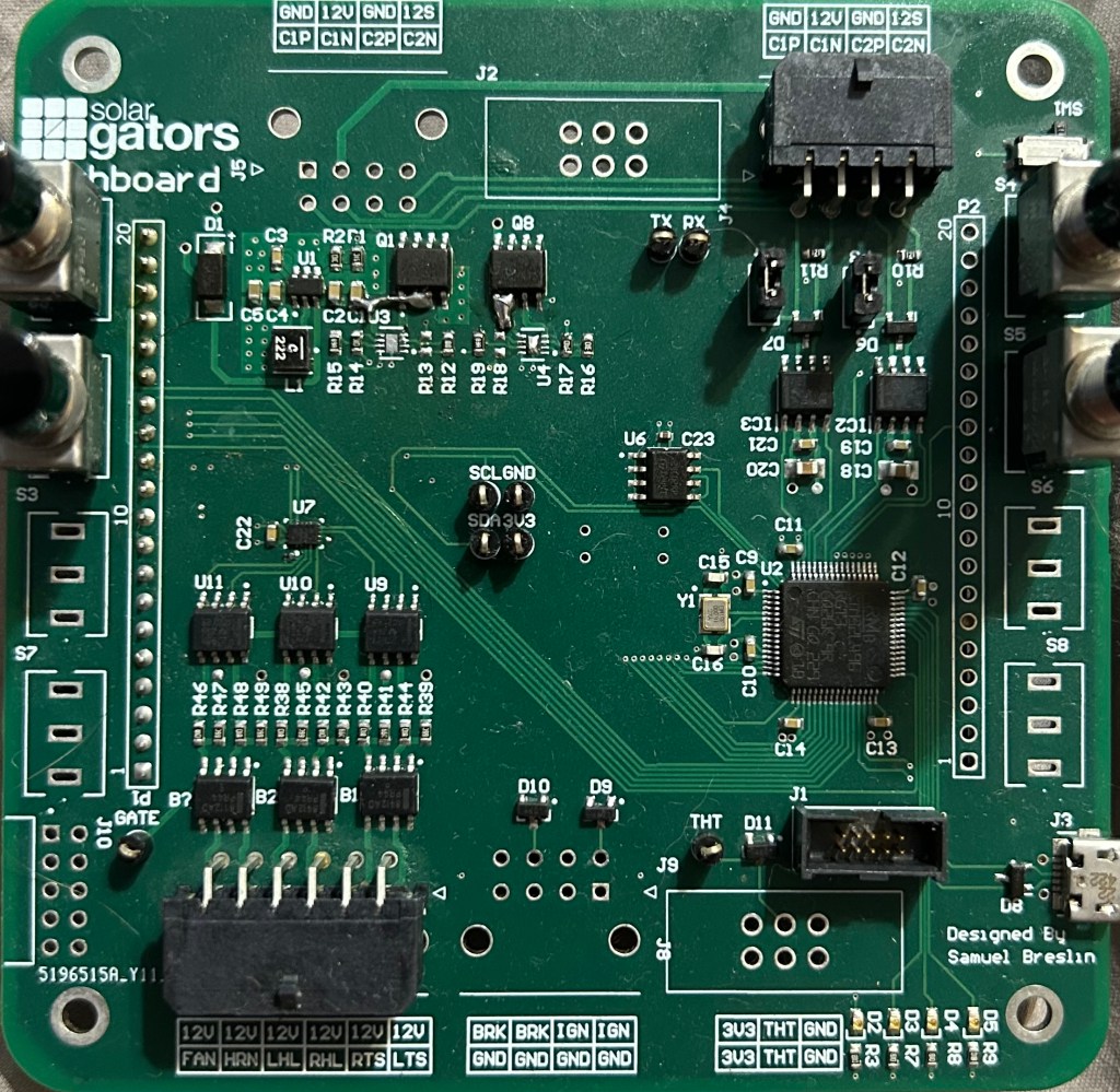
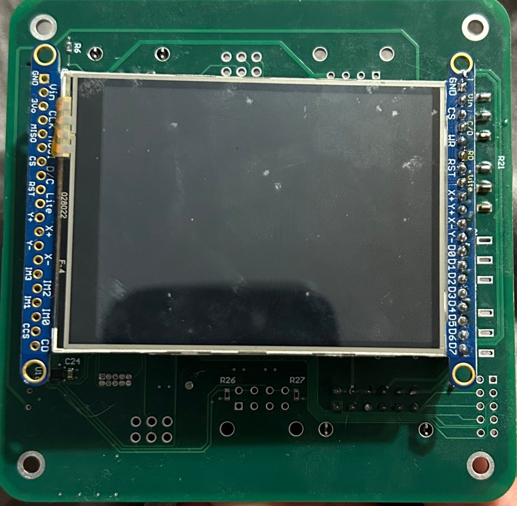
The Solar Car Dashboard is one of my favorite projects, completed in the first semester of my Junior Year I further developed my PCB design and Embedded Programming Skills while working on it. The dashboard is also responsible for several functions. First is driving an LCD which allows the driver to monitor various information. It also monitors several inputs including buttons mounted on the PCB itself external buttons including the brake limit switch and ignition switch, and analog inputs such as the throttle. In addition, the Dashboard controls the front headlights and turn signals as well as the horn and driver fan. The dashboard also communicates with the steering wheel over a UART connection and communicates with the rest of the car over the dual CAN Bus.
Peofrmance
One of the reasons that I am proud of this projects (and many of my Solar Car projects) is the fact that they are actual products. Most student projects are never tested further then the bench top on which they are soldered together. This dashboard on the other hand was used in the 2025 solar car race (a three day, 8 hours per day endurance race) and continued working well throughout the entire race.
Power Section
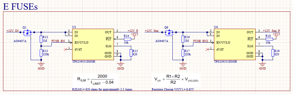
The very first step in in the Dashboard power stage is a P-Channel MOSFETs used for reverse polarity protection, Second is a E-Fuse which of course provides current limiting, as well as over and under voltage protection. This protects the board from power line transients, as well as protecting the board from shorts in the rest of the car, and protecting the car from any issues on the board.
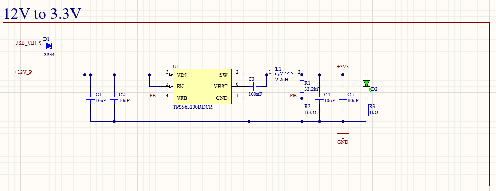
The next step a standard buck converter design based around a TI controller chip with integrated FET, the proper output capacitor and inductor are selected, along with a voltage divider for feedback and an LED for power status. On the input side, are Input capacitors and a diode allowing for the board to be powered off the USB port. While the diode is quite inefficient (something like a power mux might be better) we only care about the efficiently from the 12V supply as this is all that is used while racing.
Microcontroller
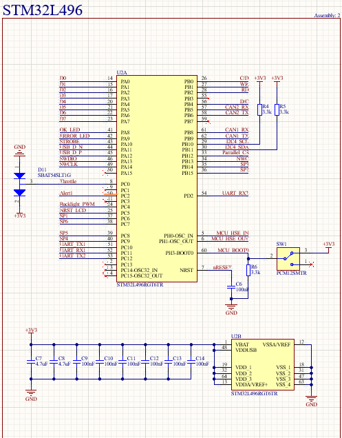
This board uses a STM32L496R microcontroller. Shown above is the STM32 Circuity used on the Dashboard of the Car. For each power pin a 100nF decoupling capacitor is used, and two large 4.7uF caps are used for bulk decoupling
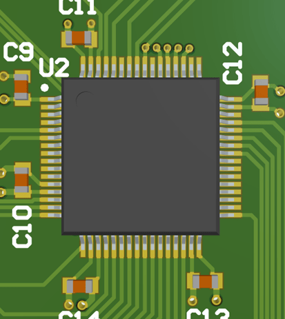
In this photo you can see the layout and routing of the decoupling capacitors as you can see each decoupling capacitor is places across a pair of +3.3V and GND pins and is placed between the pins and vias which connect to the GND and +3.3V layers.
Next are the NRST and BOOT0 pins of the microcontroller, the NRST pin is pulled high by an internal pullup resistor, thus all that is needed is a 100nF capacitor which provides filtering to avoid accidental Resets. The BOOT0 pin is pulled low thought a 3.3k ohm resistor.
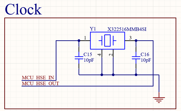
Above is the Oscillator Circuit used on most boards in the car. Here we are using the X322516MMB4SI crystal oscillator. The external oscillators are used to ensure accurate timing between multiple boards in the car which are communicating with each other at high speed.
For downloading code the I am using Serial Wire Debug also known as SWD, it uses 3 main signals, the first is serial wire clock, the second is serial wire digital input output, and the third is the microcontroller reset line, as the programmer device must have control of the STM32 reset. The SWO line is optional but allows for a greater amount of data to be transmitted from the STM32 to the programmer device. The connector is a simple 10 pin JTAG THT style connector
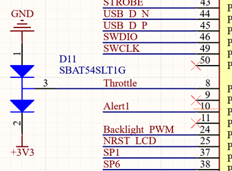
The throttle connects directly from one of the connectors to one of the internal ADCs on the micro controller. In order to protect the micro controller from Electrostatic discharge a diode array is used on the node. A current limiting resistor should also be used.
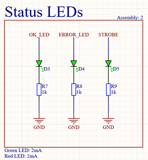
Three status LEDs are also on the MCU schematic, along with the proper current limiting resistors
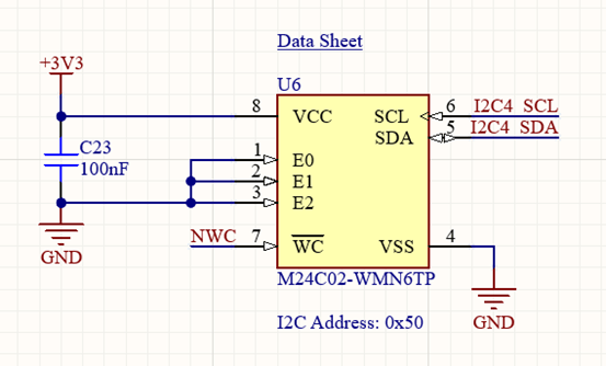
The next feature is a I2C addressable EEPROM chip, this allows for Non-Volatile Memory (Memory which lasts between power cycles). The only non-volatile memory built into the STM32 is the flash memory which is used for storing program code. (In theory you might be able to use any spare flash memory for storing whatever you want but its not recommended). The EEPROM simply requires a I2C connection, and a GPIO connection for read write protection, and a 100nF decoupling capacitor.
CAN (Controller Area Network) circuity
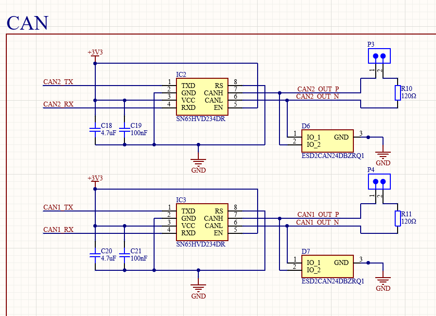
Each board on our car has two independent CAN transceivers allowing for a Dual CAN bus system. this is done for reliability. Each Transceiver is paired with two decoupling capacitors, a TVS diode, and a 120 ohm termination resistor, configurable with a jumper.
12V load control
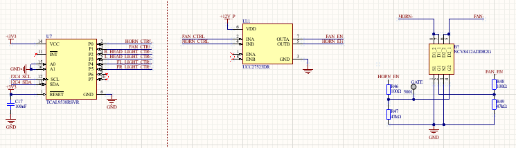
The dashboard was responsible for controlling a number of 12V loads including the horn, driver fan, and front lights. To do this a GPIO expander, Three Dual Channel gate drivers, and three two channel NMOS ICs were used. Pictured is the GPIO expander, and one of the gate drivers/NMOS ICs.
Digital Inputs
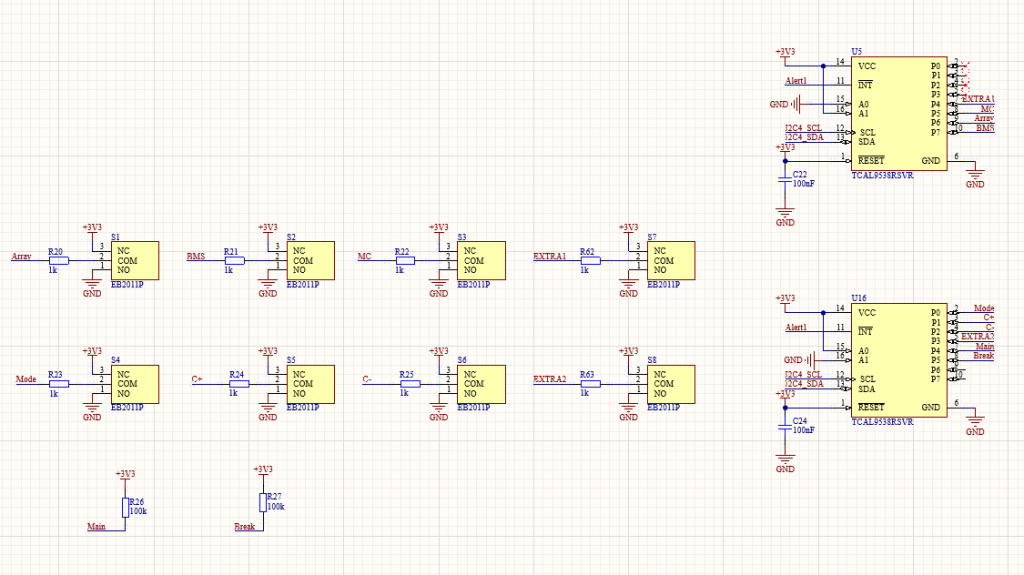
The dashboard was also responsible for monitoring a number of digital inputs, in the form of 8 board mounted buttons, the brake peddle sensor, and the ignition switch. Again using GPIO expanders.
