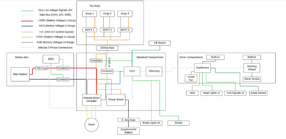
As the Electrical Chief Engineer for the UF Solar Car Team it was my responsibility to dictate the electrical Architecture for our Fourth Car (Flare). This was based greatly from what I learned contributing to our third car (sun rider) and from the many amazing team alumni.
Battery Box
Inside the battery box is a 29s10p lithium ion battery pack, a high and low side contactor, main fuse, and custom battery management system
Main Electrical Compartment
The main electrical compartment, contained the following devices:
- Motor Controller
- Maximum Power point trackers
- MPPT pre-charge Circuit
- Vehicle Control Unit *
- Power Board *
- Telemetry Board *
*Indicates custom printed circuit board
Driver Compartment
The driver compartment, contained the our custom Dashboard PCB, and steering wheel PCB which was of course embedded in the steering wheel. As well as the Throttle and Brake Pedal sensors.
Solar Array
The solar array was a four square meter array consisting of 3 sub-arrays and 29 modules. producing over 1KW of power.
Communications/Wire Harnessing
All Custom PCBs and the MPPTs communicated with each other over CAN Bus. The main wire harness which connected all boards in the car consisted two four conductor shielded cables and use Molex Microfit connectors. The signals carried are as followed
- CAN High 1/2
- CAN Low 1/2
- GND 2x
- +12V Main
- +12V Supplemental
